Building a Large Dobsonian Telescope
The story of my quest to build a large, portable telescope for visual use.
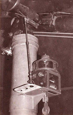
The clock drive of the University of Liverpool Cooke refractor in 1978
Background: Why a Dobsonian?
I have been fascinated by astronomy since childhood. I first learned to recognize the stars (with my Dad’s help) at the age of 8 from a little Quiz-Me book called simply ‘Constellations’ and I remember giving a short talk to my class about the solar system around the same time. My 14th birthday present was a 3¼” Prinz reflector from Dixons which I used to observe from my parents’ suburban garden in Liverpool in the 1970s. I joined the BAA in 1972 and started reading Sky & Telescope the same year. Soon my ambition was to own a sizeable telescope mounted permanently in an observatory (it should be noted that ‘sizeable’ in those days typically meant a 12″ reflector) but that would have to wait until I had my own house and sufficient funds.
At university I revived the dormant AstroSoc which had a 4½” Cooke refractor in an observatory atop the Chadwick Tower (see photo at left). We used the scope to peer through Liverpool’s light polluted skies at such gems as the Double Cluster in Perseus.
During this time I read an article in Sky & Telescope (‘Have Telescopes, Will Travel’, April 1980) by an ex-monk called John Dobson who made large (typically 18″) low-cost newtonian telescopes that worked extremely well and were even transportable. He would grind his mirrors from port hole glass and make the scopes out of plywood, cardboard and drainpipe. This was the start of a revolution in amateur telescope making that would come to fruition in my own case some 20 years later.
My career after university saw to it that I was never in one place very long. Even when I owned my own house I was often working abroad for long periods – not a situation compatible with building an observatory. However in 1990 I was persuaded that a 10” SCT was portable enough – and quick enough to set up and take down – to allow me to observe regularly.
That was a mistake! Lugging the scope downstairs from a second floor apartment soon causes enthusiasm to evaporate, and I ended up using the scope far less than I had hoped (this of course is a common story in amateur astronomy).
My next scope was a Questar 3½. This was far more suited to my nomadic lifestyle, as well as being a beautiful instrument, a pleasure to use, and with a setup time in seconds rather than minutes I found I used it far more than the 10″ SCT. Of course, its smaller aperture could not compete with a 10-inch, but having a scope that you use often is far preferable to having a large scope that only comes out a few times a year.
Then in 1998 I read Dave Kriege and Richard Berry’s excellent book The Dobsonian Telescope (Willmann-Bell 1997), a manual for building large Newtonian reflectors to an optimized Dobsonian design. This, I decided, would be my next scope, and the following is the story of how I built it.
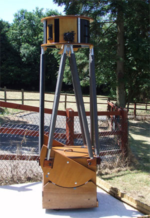
The completed Scope
What is a Dobsonian telescope?
The Dobsonian is a Newtonian reflector mounted in a low-cost, lightweight alt-azimuth mount. It is not motorized and is therefore intended for visual use only, rather than astrophotography. Due to careful design it is well balanced and can be easily moved with one hand to follow a celestial object without jerky movement or backlash.
It features a thin primary mirror housed in a low-profile mirror box made of plywood, which sits on a flotation cell that minimises flexure and allows good air circulation. A sling made of seatbelt webbing supports the mirror and prevents it from sliding as the tube tilts from the vertical.
Dobson used a hinged tailgate that allowed easy access to remove the mirror for transport, and cardboard form tubing (of the type used for moulding concrete) for the tube, but in the Kriege design the flotation cell is more sophisticated and is attached to a steel frame (still called the tailgate) that does not hinge. The mirror box supports a truss tube of aluminium poles, at the end of which sits a secondary cage of plywood and aluminium. The mirror box sits in a rocker box that allows movement in altitude using two very large semi-circular bearings whose surfaces are covered with worktop laminate that glides over teflon pads attached to the rocker. The rocker box itself sits on a ground board on which it rotates, again using worktop laminate riding on teflon pads for the bearing surfaces. The scope can be set up and taken down in a few minutes and stowed in the back of an estate car or pickup truck for transport.
A Dobsonian is a low-cost solution in comparison with manufactured instruments of similar size, but there are still significant costs when building a large one, for example the optics. For me, another cost was tooling up for the job and fitting out a workshop for the project. Having to invest in this equipment was a factor in the decision on what size scope to build. After all, I would need practically the same equipment whether I was building an 8-inch or a 24-inch telescope. For a first project of this type the wise choice would be not to go too large. The dobsonian range tends to start at 8 inches aperture, but I already owned a 10″ SCT, so I wanted something that would show me a lot more than that. Perhaps a 14″ would have been the ‘right’ choice: it doubles the light grasp of a 10″, and is the size most often favoured by John Dobson himself, as being large but manageable. On the other hand, aperture fever comes along and whispers ‘why not go as large as you can?’
The next decision was whether to grind my own mirror or buy one. I had some experience of grinding a 6″ mirror while at university and had started on a 9″ (which remains unfinished). However I wanted a short-focus Dobsonian (f/4 or f/5) and these are more difficult to figure (figuring is the delicate final stage of polishing the mirror that changes its natural spheroidal shape into a paraboloid).
I found that the largest mirror blanks made in the UK at the time were just under 20″ in diameter; this was considered mid-size in the book, but of course everything in the US tends to be bigger, including the pick-up trucks on which many of these scopes are transported! My scope had to fit in the back of an estate car.
On the basis that this was probably going to be my one and only Dobsonian construction project, I decided to go for a 20″, and to buy a finished mirror rather than spend months grinding my own with no guarantee of the quality of the finished result.
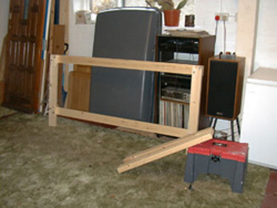
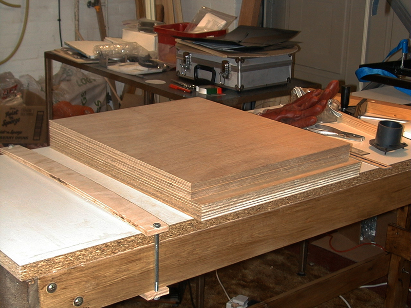
Before I could start the telescope, I needed to equip a workshop. The house I had at the time had a large integral double garage which would be ideal: good lighting, plenty of power sockets and internal access from the house. My workbenches consisted of our old kitchen units, so to create more workspace I made a simple bench out of a length of kitchen worktop and a simple wooden frame, bolted together (no fancy woodworking joints I’m afraid!).
As we had re-carpeted part of the house I also put some of the old carpet down in the workshop, which made it a little more comfortable to work in during the winter. I bought a bench circular saw, a vertical drill, a router and various other bits of woodworking and metalworking equipment. I then turned to the materials for the telescope itself.
Sourcing the Materials
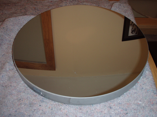
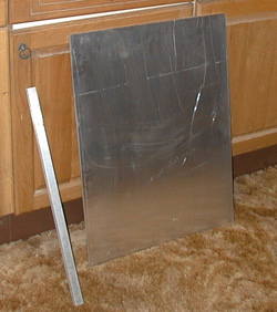
The 20″ mirror. Note how thin it is – the aspect ratio (diameter to thickness) is over 12, compared with about 6 for earlier mirrors. This helps it to cool faster, but means it must be carefully supported to avoid deformation.
I ordered a 20″ f/4 mirror from Beacon Hill Telescopes, which was supplied with an 89mm elliptical flat (this being the minor axis). I believe the secondary should be bigger to fully illuminate the field of view but it seems to deliver good images. With the optics ordered I started to plan the project in detail. The book provided dimensions for several sizes of Dobsonian, including a 20″ f/5, however as my mirror was going to be f/4 I had to recalculate all the dimensions. Apart from the obvious impact on the length of the truss tube, the shorter focal length has other subtle effects, such as on the secondary mirror offset.
When it came to sourcing the materials to build the scope, I soon came across a recurring problem. They say that Britain and America are two nations divided by a common language, but beyond that I discovered how much Americans talk in brand names! It seems this habit is far deeper ingrained in American language than it is in Britain. Admittedly some brand names have become part of the language here (‘I need to hoover the carpet’) but this is nothing compared with colloquial American: ‘Pass me a Kleenex’, ‘Don’t write on the Formica with that Sharpie!’, ‘I need a Tylenol.’ And so on.
Aluminium bar and sheet waiting to be turned into a mirror flotation cell
I therefore found myself looking for, among other things, Kydex, Apple-ply, Ebony Star, Ripstop, Nylok nuts and a host of other branded items I had never heard of, most of which were not available in the UK. However in most cases it was fairly easy (though often time-consuming) to find substitutes. I selected Far East marine ply for the mirror box, rocker box and secondary cage rings, and mahogany for the hardwood blocks and feet. I found that Ebony Star laminate was available from kitchen suppliers in the UK, and I managed to buy some Ripstop nylon while on holiday in Florida (though I’ve since found it near home).
There was an aluminium supplier on the Isle of Man where I was living at the time, where I sourced the tubing for the truss poles, and the sheeting and bars needed for the mirror flotation cell. More common supplies like square steel tubing (or box-section) were easy to obtain, and some things I had to send away for, such as threaded inserts, plastic knobs and teflon pads.
The only other parts that were not home-made were the secondary cage clamps.
Construction of the Mirror Cell
The first part to be made was the tailgate (so named because in Dobson’s original design the rear door of the scope was hinged to allow the mirror to be removed for transport). In the Kriege & Berry design the tailgate is a steel frame for rigidity, on which the flotation cell is mounted. I had no welding kit or experience but a neighbour of my in-laws allowed us to use his kit, as well as an electric saw for cutting the steel. With the steel box sections and edge pieces cut to length and bolt-holes drilled, I then made a wooden jig to hold all the steel in place, which made the welding relatively straightforward.

Steel to be welded into the tailgate.
A cardboard mirror template is at left and The Book is never far away…
A key aspect of the Dobsonian design is a thin primary mirror. The classic thick mirrors of the past had a thickness about one-sixth of their diameter to prevent them deforming under their own weight, but modern Dobsonians have mirrors only about one-twelfth as thick as their diameter. This not only keeps weight down but means they also cool down quicker, and so deliver crisp images sooner than a thicker mirror would.
However a thinner mirror is more prone to flexure unless properly supported in its flotation cell. Ultimately the mirror’s weight is carried by three bolts attached to the tailgate, which also serve to adjust collimation. A small mirror (say 6″) can be supported by just three contact points because it does not flex much under its own weight, but with larger mirrors the number of support points needs to increase to ensure the mirror doesn’t sag (remember, you don’t need much sag to affect something as small as the wavelength of light). The rule of thumb for the number of flotation points is 1.5 times the diameter-to-thickness ratio (in my case 12) meaning I needed an 18 point flotation system. Deciding where these 18 contact points should be is no trivial task, since each needs ideally to carry an equal share of the weight of the mirror.
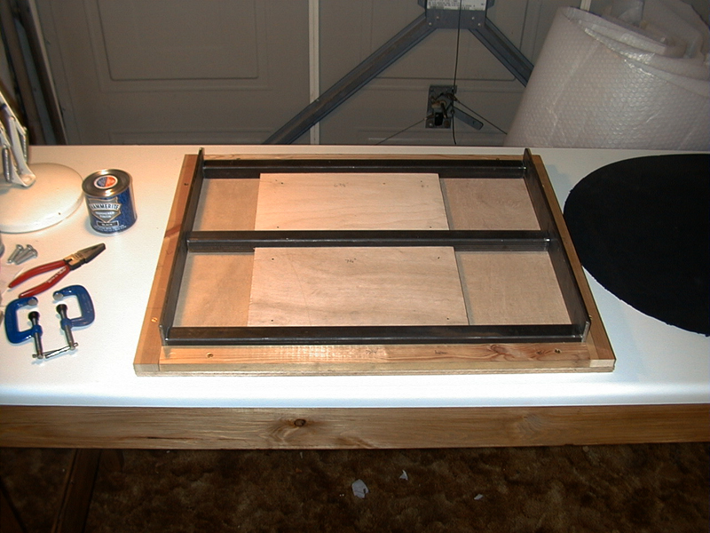
A jig makes the welding much easier
How is this arranged? Each of the collimation bolts has a balance bar sitting on top of it; at each end of the balance bar a metal triangle is mounted; and at each apex of each triangle a felt pad is glued, and these are the contact points. Three bars times two triangles times three pads gives our 18 points of contact. The triangles are isosceles, and they are arranged in a circle, pointing towards the centre.
Now the precise placement of the pads, and hence the dimensions of the triangles and bars, can be calculated using a utility such as CELL, a public domain program written by David Chandler. The program no longer seems to be available on David’s website but it can still be downloaded from The Astronomical Unit. However, being an old DOS-based program, getting it to run under modern versions of Windows could be difficult.
The CELL utility takes the mirror dimensions and required number of contact points and calculates the sizes of the triangles and bars for you so that each pad will carry an equal share of the mirror’s weight.
The triangles are made from 6mm aluminium sheet, and the bars are solid aluminium, all cut out by hand with a hacksaw. The couplings between collimation bolts, balance bars and triangles are deliberately loose to allow them to jiggle around and distribute the weight evenly, but the triangles are attached to a ring of flexible plastic (‘Kydex’) which prevents them moving out of position. The felt pads I used were just self-adhesive ornament feet.
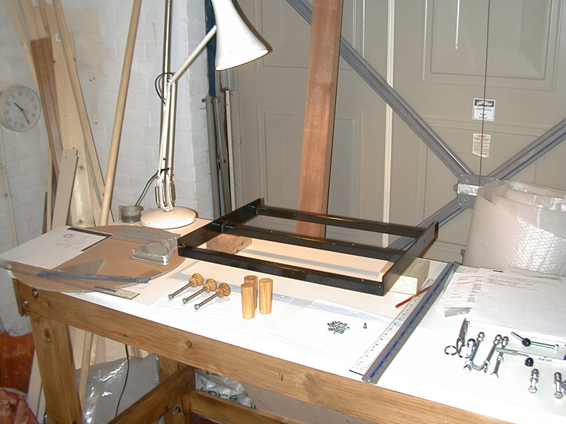
The finished and painted tailgate with parts for the flotation cell, awaiting assembly.
As the mirror tilts with the telescope, some of its weight acts through its edge and without restraint it would slide off the flotation cell. This is prevented by a sling made out of seatbelt webbing, which is suspended from two bolts at the sides of the mirror. Turning these bolts adjusts the tension in the sling so that it starts to take the weight of the mirror as it tilts, and prevents it moving. Since the Dobsonian is an alt-azimuth mount the tube does not rotate about its axis, so the same edge of the mirror is always at the bottom, where the sling is attached. Another ingenious invention by John Dobson!
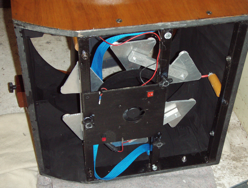
The flotation cell can be seen in this view of the completed mirror box (minus mirror), seen from below during refurbishment.
As no photo of the completed flotation cell was taken during building, the image at left shows the tailgate and cell during refurbishment after some years of use. The sling, balance bars, triangles, felt pads and Kydex ring can all be seen, along with the wooden retaining pegs that prevent the mirror slipping sideways during transport and the red safety restraints that prevent it tipping forward at low elevations. The cooling fan and wiring can also be seen.
Please note that the information presented here is not intended as a step by step guide to constructing a telescope: it is just the edited highlights of my own project. For anyone interested in building such a telescope I can do no better than recommend the book that my project was based on: The Dobsonian Telescope (Kriege & Berry, Willmann-Bell 1997)
Construction of the Secondary Cage
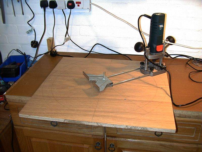
The router set up for cutting the rings for the secondary cage.
The cage holds the secondary mirror in its holder, along with the focuser, and finder-scope. Its construction is lightweight: two parallel plywood rings held about 12 inches apart by aluminium tubing, with a flexible plastic body to keep out the light.
The plywood rings are cut out of sheets of marine ply using a router, a device typically employed to make patterned grooves in wooden furniture, but here used mounted in a jig that allows it to orbit the centre of the circle that forms the rings. Two circular cuts are made, and the difference in their radius determines the width of the rings. The cuts must be made carefully, using three or four ‘orbits’ of the router, and a good tip is to leave two small ‘islands’ of wood on opposite sides of the rings which hold things in place until the rest of the cut is completed. They can then be carefully removed with a final cut.
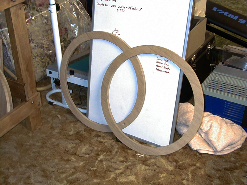
The plywood rings cut out and ready for sanding and varnishing.
Once the rings are made, four struts are cut from aluminium tubing. These define the height of the cage, which should be sufficient to prevent scattered light from entering the eyepiece. A tube cutter was very handy for this job, as it gives a perfectly square edge, and it will be used again when making the truss poles. The struts are bolted to the rings using threaded inserts that are pushed into the ends of the struts, giving an M6 threaded hole for the bolts.
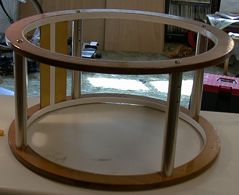
The cage takes shape once the rings and struts are bolted together.
One or two panels of thin plywood are also needed, braced between the two cage rings. One is required to hold the focuser, and it needs to be mounted precisely perpendicular to the cage diameter to ensure the focuser is square on the tube (although focusers can be adjusted or shimmed if necessary). As I chose a 2″ focuser, this was the size of hole I drilled through the panel to accommodate the converging light cone.
The other panel can be used to mount a finder if desired, however a lightweight finder like a Telrad can just be mounted on one of the struts.
The next component of the cage is the secondary mirror holder, or spider. This is best sourced commercially in my view, and they are available in three and four leg designs, with straight legs or curved (the latter eliminates diffraction spikes). I went for a four leg design as this makes it easy to mount one foot of the spider on each strut of the cage.
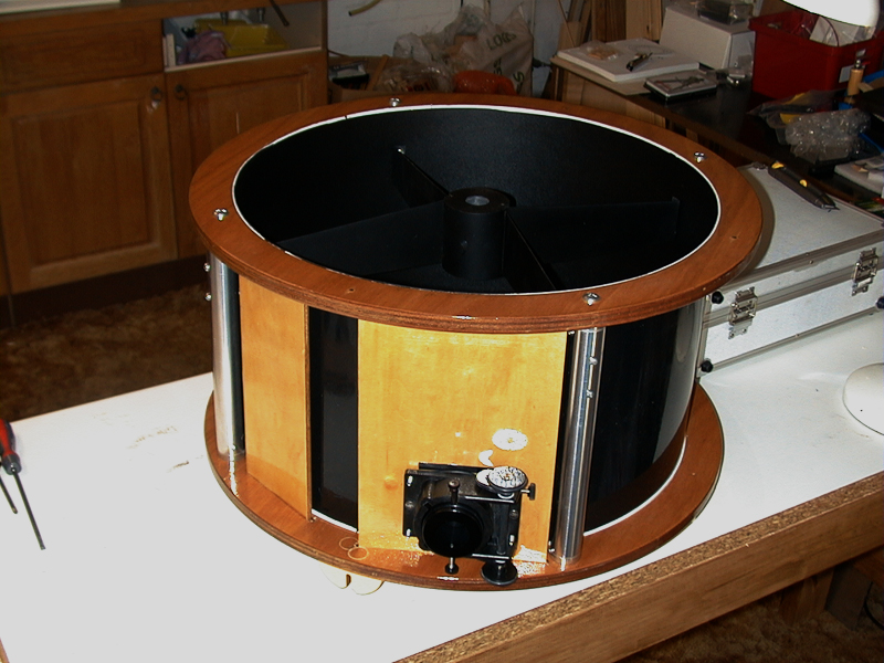
The finished cage
The cage bodywork is made of Kydex plastic. This is a flexible, waterproof acrylic-PVC sheet available in various thicknesses. I used 2mm black sheet, shiny on one side and matt on the other, and in this thickness it is certainly not flimsy but is flexible enough to be bent around the inside of the cage. Its shiny side looks good on the outside and the matt finish on the inside helps prevent internal reflections. It is attached to the plywood rings with double sided tape.
The focuser is mounted on the plywood panel. I located the focuser toward the bottom end of the cage to minimise the effect of any stray light entering the top of the tube. It is important to use a low-profile focuser, otherwise the drawtube when racked fully in will project into the lightpath and cause a slight degradation in the image. On the other hand the focuser needs a good range of movement to accommodate the different eyepieces that will be used; the calculations that determine the focus range have to be done carefully, taking into account all the eyepieces, coma corrector and barlows that may be used with it, otherwise you may find that the finished telescope cannot bring some eyepieces to focus.
The only other hardware on the cage are the attachments for the truss poles and a hook for hanging counterweights: the latter is necessary because balance is calculated for the heaviest eyepiece that will be used, and when using lighter ones there is a tendency for the front of the scope to rise upwards. This is easily rectified by hanging an appropriate counter-weight from the hook.
Construction of the Mirror Box
Far East marine ply. Hard-wearing, easy to work and attractive.
The book spends some time discussing the best plywood to use, recommending brands such as ApplePly and Baltic Birch which I was unable to source in the UK. Instead I opted for Far East Marine Ply and obtained several large sheets of 7/8″ thickness. This proved to be an excellent material both to work with and in appearance, once several coats of exterior varnish had been applied. The plywood is used for the mirror box, secondary cage rings, the main altitude bearings and the rocker box.
Before the box can be made, its height has to be calculated in order that the telescope will be balanced. The design of this scope places the balance point at the top of the mirror box; its depth therefore has to be calculated so that the weight of the mirror, tailgate etc balances that of the secondary cage. For this calculation we need to know the weight of all the components, and the distance between the primary and secondary mirrors. These can all be measured or calculated – not forgetting to check the focal length of the primary mirror. A nominal 20″ f/5 mirror may not have a focal length of exactly 100″: often the optician will deliver a mirror slightly different from the nominal f-ratio if figuring and testing produces a very good curve, rather than destroy it for the sake of ½” difference in focal length.
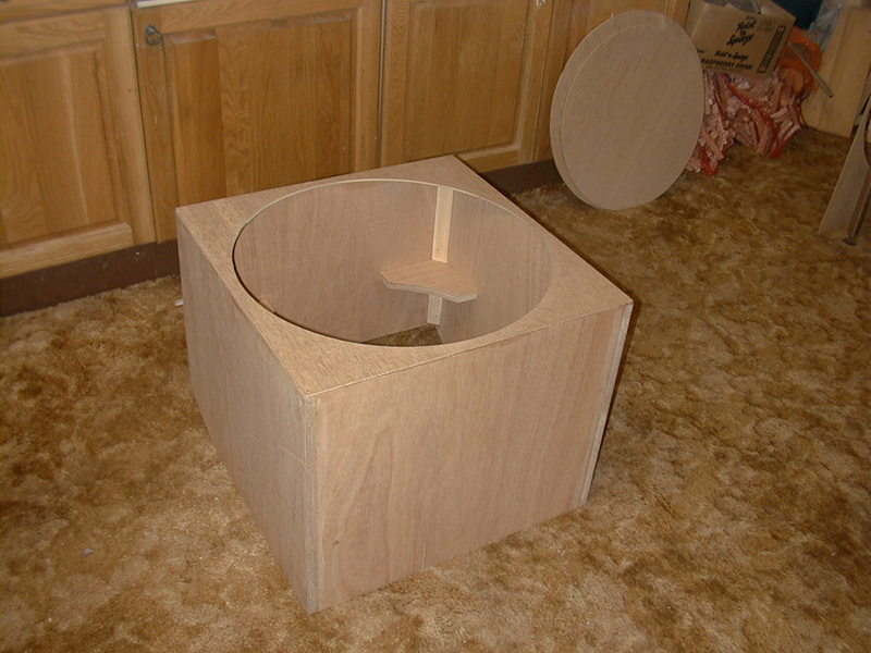
The mirror box, glued but unvarnished. Note the corner bracing inside, and the circular dust cover behind.
The mirror box has to be both strong and stiff – it really is the central component of the telescope as it has to support the altitude bearings and the truss tube with the secondary cage on top. It is strengthened with corner braces and gussets, and the steel tailgate adds a lot of stiffness once bolted in place. I found that attention to detail was the key to a successful outcome; not being very experienced in woodwork I practised on offcuts until I learned how much to allow for the thickness of the sawblade and so on. I took trouble with all the sawcuts and drilling to ensure that the wood was cut exactly to the right size and the holes were in precisely the right places. Only in this way can you hope to end up with a box with straight edges and square corners!
The mirror box has no bottom side, as the tailgate is bolted into the bottom leaving the air free to circulate and cool the mirror.
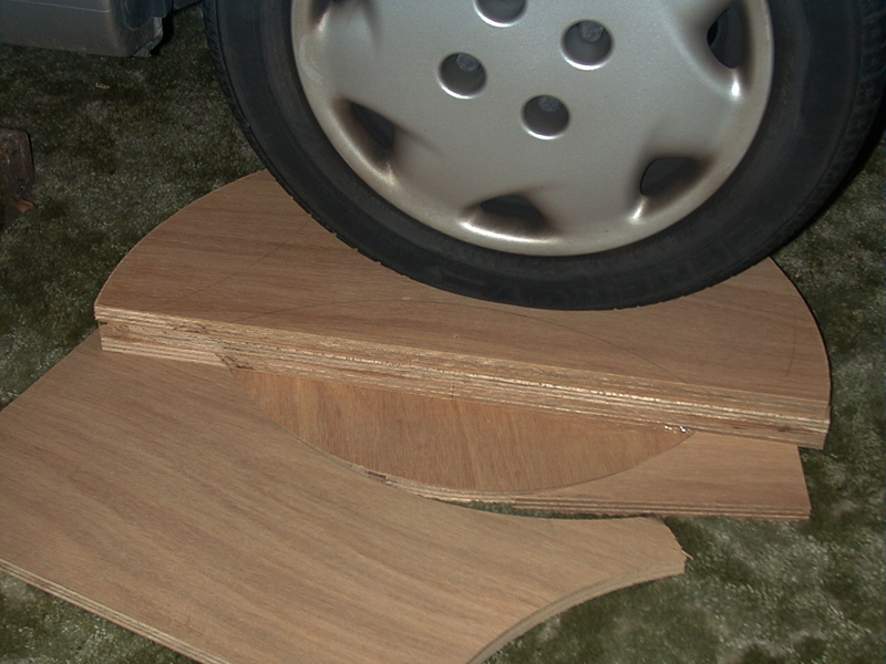
The double-thickness bearings being bonded overnight under a suitably heavy weight! The top layer is an offcut protecting the actual bearings from being marked.
A key distinction of the Kriege design are the massive altitude bearings which make for much smoother movement in altitude. These are made from the same ply as the mirror box, but with double the thickness. After cutting out the four semi-circules with the router, they are bonded together in pairs with wood glue and left to dry overnight with a heavy weight on them.
The edges are then covered with worktop laminate: I was pleasantly surprised to find one of the brands recommended in the book – Ebony Star – which gives the ideal amount of ‘stiction’, enabling the scope to be moved easily and smoothly yet to hold its position once let go.
The completed mirror box. The cut-outs in the bearings are for the mounting blocks of the truss poles. Note the laminate glued to the bearings.
With three coats of varnish the plywood faces of the mirror box begin to look very attractive. The bearings are bolted on the the sides of the box at an angle to allow the scope to point from the zenith to about 10 degrees above the horizon. The cut-outs in the bearings are to allow mounting of the blocks holding the truss tube struts.
The top of the box is just thin ply with a circular hole large enough to allow the mirror (and a pair of hands) to pass through. The dust cover is made slightly larger than the hole and, also being circular, cannot fall through on to the mirror.
A cooling fan is mounted behind the mirror cell. I used a fan unit from a PC configured so that it draws air away from the back of the mirror and blows it out to the sides. It is powered by a 12V rechargeable gel battery mounted on the steel tailgate – this also provides power for the anti-dew heater.
The Truss Tube
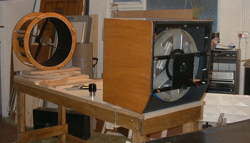
Mirror box and secondary cage set up for First Light. The mirror cooling fan is also visible.
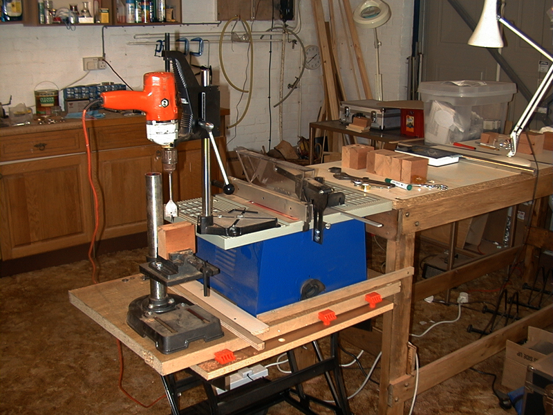
Jig for boring out the hardwood blocks for the truss poles.
The merits of the truss tube design are discussed at length in the book. It is lightweight, it resists flexure and is easy to transport and assemble. It comprises eight aluminium poles held in hardwood blocks mounted on the mirror box. The secondary cage is attached to the top ends of the poles.
Rather than calculate the length of the poles from first principles it is much more exciting to set up the optics for ‘First Light’, bring an image to focus and measure the distance between the mirror box and secondary cage.
The arrangement shown in the picture (which also shows a good view of the mirror flotation cell and cooling fan) has the mirror box tilted very slightly to prevent the mirror falling forward onto its restraining pegs. The secondary cage is positioned carefully on the optical axis and, by opening the garage door, I was able to view a communications mast on a hill about a mile away.
Bringing this to focus enabled me to make the crucial measurements, remembering to adjust for the fact that the mast was at a finite distance (astronomers are used to viewing everything at infinity). Using the old school formula 1/f = 1/i + 1/o (where the terms are the inverse of the focal length, the image distance and the object distance respectively) this modified the focus position by only 1/10th of an inch, however if the object had been only a quarter of a mile away the focus would have shifted by almost half an inch: the poles would have been cut too long and some eyepieces may have been unable to reach focus.
If the poles are too long, the focal plane moves inward towards the axis of the scope. If they are too short it is pushed out, potentially beyond the furthest outward travel of the focuser. But either problem can be fixed: poles that are too long can be shortened (I had to do this when I wanted to take photos through the scope with my DSLR) while for poles that are too short, an extension tube can be inserted into the focuser to increase backfocus.
Although not shown in this section, the truss poles are well seen in the banner photo at the head of this article, and in other images near the end.
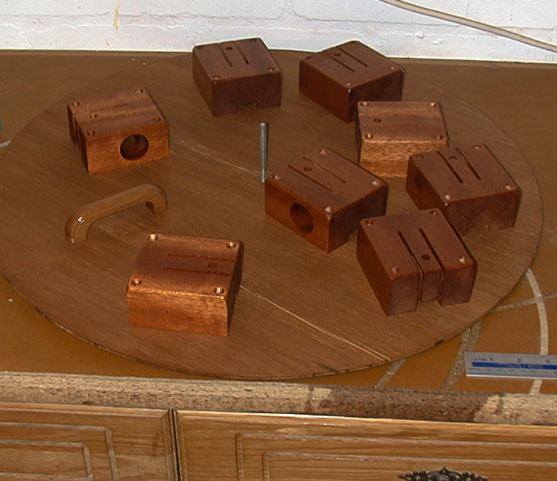
The finished blocks
The truss poles sit in hardwood split blocks that can be tightened to hold the poles firmly in place. From a length of teak I cut eight blocks which were then bored to exactly the same depth with a 1¼” spade drill mounted in a vertical jig. Unfortunately my vertical drill did not have sufficient vertical range for the spade bit I was using and the depth of the holes, so I used a hand drill mounted on a jig instead. The blocks have splits cut into them to create a natural spring, against which a knob is tightened on a bolt to provide the tension to hold the truss pole firmly. Full details on how to make the blocks are in Kriege & Berry; the finished items can be seen in the picture.
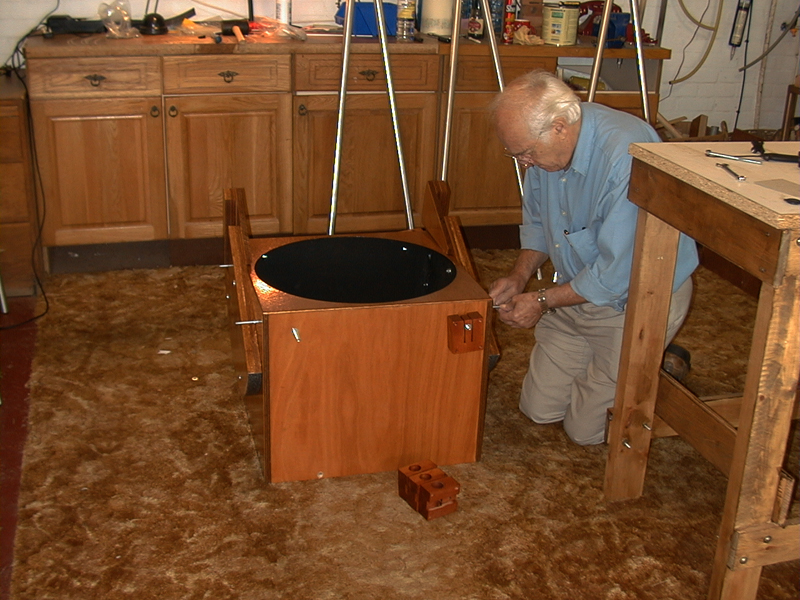
Always get as much help as you can! My Dad attaching the pole blocks to the mirror box.
The blocks are mounted on the tension bolts that will be tightened to grip the truss poles. The blocks are loosely positioned at the approximate angle necessary to bring each pair of truss poles within an inch of each other at the secondary cage. Later the poles will be fitted into the blocks to refine the mounting angle, then the blocks are screwed into their final position.

The poles sit in seats on the base of the cage, and are clamped in position with wedges and cam levers. A soft cloth bag protects the secondary mirror.
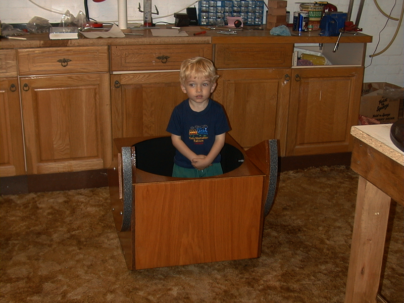
My son Jeff was also keen to help Grandad and Daddy with the telescope. Here he is testing the strength of the mirror box…
Rocker Box & Finishing Touches
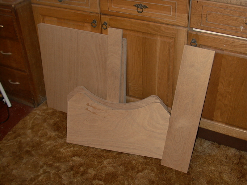
The parts for the rocker, awaiting assembly.
The rocker box provides a solid container for the mirror box and allows movement in altitude and azimuth. Altitude movement is via the semi-circular bearings on the side of the mirror box which allow the entire scope to swing up and down. Movement in azimuth is achieved by the rocker box rotating bodily on a ground board, carrying the scope with it. Its sides are therefore of double-thickness ply, curved with the same radius as the altitude bearings that they support.
The mirror box bearings are covered with Ebony Star worktop laminate which rides on teflon bearings attached to the curved rocker sides.
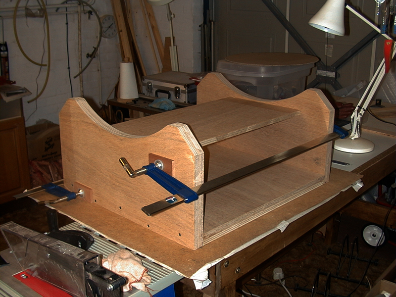
At left is seen the rocker box during assembly, clamped while the glue sets. The horizontal board temporarily holds the sides vertical.
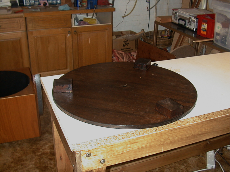
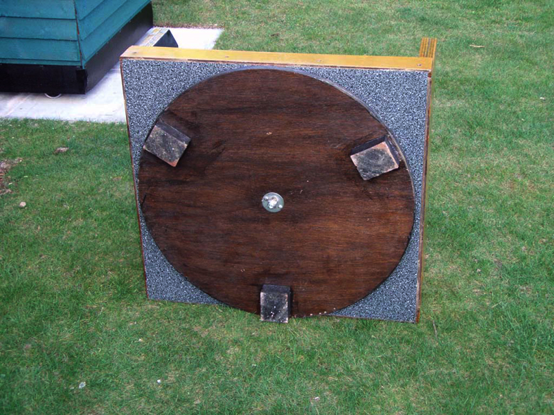
The ground board, upside-down showing the three feet which rest on the ground. At left the altitude bearings are seen with the laminate glued in place.
The bottom of the rocker box is also covered in laminate and this enables it to swing in azimuth, riding on four teflon bearings fixed to a ground board, a circular board with three hardwood feet that sit in contact with the ground. The ground board is never normally seen so its appearance is not important, but it needs protecting against wet ground, as in this case where a woodstain has been applied.
The teflon bearings are mounted on the upper side of the board, three above the feet and one above the central bolt hole, where they bear the weight of the entire scope.
Groundboard fitted on rocker box.
This image was taken during a subsequent refurbishment of the scope, as can be seen from the weathering of the feet.
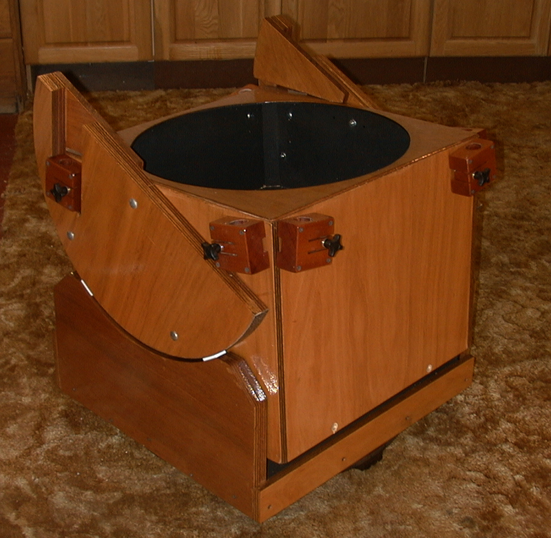
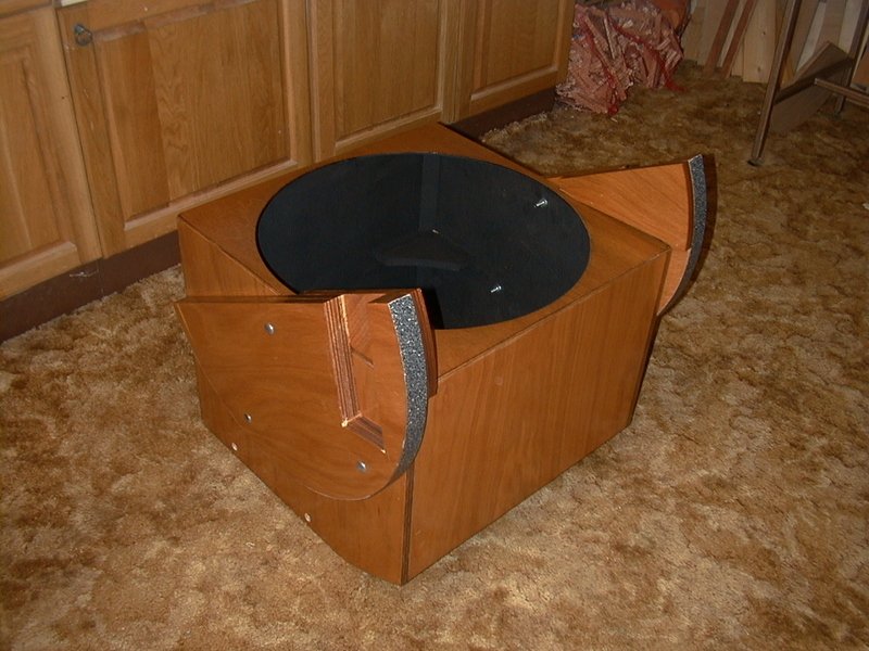
Mirror box in rocker
The completed mirror box mounted in the rocker. Note the white teflon pads under the altitude bearings.
The inside of the mirror box and rocker have been coated with matt black paint.
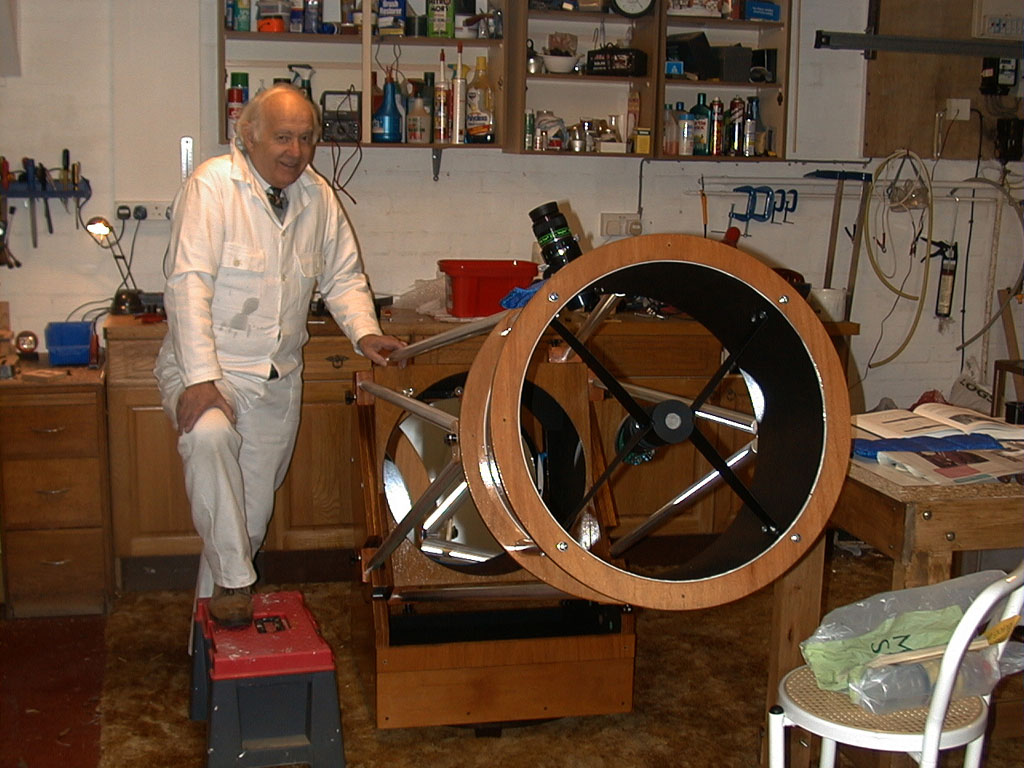
My Dad with the completed telescope
The final stage is to install the optics, and hope that the calculations done at the design stage result in a balanced scope, and images brought to correct focus!
The Ripstop nylon mentioned above is used to make a light shroud which fits snugly over the truss tube and bottom ring of the secondary cage to keep out stray light. It attaches to the knobs on the hardwood blocks with loops of elastic. Making the shroud may require the co-operation of someone with more sewing skills than I possess.
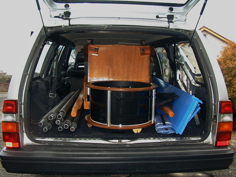
The entire scope stowed in the back of a Volvo
Finishing Touches
For moving the rocker/mirror box a pair of wheelbarrow-like arms screw into the sides of the rocker, allowing it to be tilted up and wheeled from the vehicle to the observing site.
Other finishing touches include:
• drilling a hole through the base of the rocker into the ground board. Dropping a nail through this hole will prevent the scope being slewed around by gusts of wind during the day while unattended.
• a similar hole can be used to hold the scope at a desired altitude.
• a Telrad (unity-power finder) is useful mounted either on the secondary cage or the mirror box.
• a pair of ramps will be needed for loading the scope into a vehicle.
Shown at left along with the scope are the truss poles and loading ramps ready for transport to a dark sky site.
THE END